Bend Rad For 16g Sheet Metal

How To Choose Cut And Bend Sheet Metal Make

Home Made Sheet Metal Brake Sheet Metal Brake Metal Bending Tools Metal Working Tools

Homemade Sheet Metal Bender Sheet Metal Bender Metal Bender Sheet Metal Brake

Eastwood Metal Cutting Tools How To Cut Sheet Metal To Thick Plate Youtube

How To Bend Sheet Metal 13 Steps With Pictures Wikihow

10 6 Aluminum Steel Metal Trim Siding Brake 26g Steel Stand Slitter Included Ebay Siding Trim Sheet Metal Fabrication Metal Trim

When metal is bent the top section is going to undergo compression and the bottom section will be stretched.
Bend rad for 16g sheet metal. Understanding the bend allowance and consequently the bend deduction of a part is a crucial first step to understanding how sheet metal parts are fabricated. You only have to insert interior angle flange lengths k factor inside radius and material thickness. With this free online tool we quickly get the sheet metal bend deduction and therefore the sheet metal blank initial flat length from the finished part measurements. Cells on the right will output the desired values.
The bend allowance and bend deduction are two measures that relate the bent length of a piece of sheet metal to the flat length. When the sheet metal is put through the process of bending the metal around the bend is deformed and stretched. The bend allowance describes the length of the neutral axis between the bend lines or in other words the arc length of the bend. Also known as press braking flanging die bending folding and edging this method is used to deform a material to an angular shape.
Since commercial sheet metal bending can be done with less concern for stresses caused during forming operation the radius can be near zero for thin sheet metal. It is possible to choose other bends if you require but additional lead time and tooling charges may apply. When working with sheet metal it is common for the term gauge to be used someone unfamiliar with the gauge system may not understand what is meant by 18 gauge steel for example. Therefore the bend allowance added to the flange lengths is equal to the total flat.
The k factor in sheet metal working is the ratio of the neutral axis to the material thickness. The bend radius you select may not be available if the geometry of the part will not allow us to bend with the specific tooling required to achieve that radius. With coining and bottom bending the punch nose radius establishes the inside bend radius value to be inserted into the formulas for the bend deduction. The minimum bend radius data shown in these charts is measured to the inside of the bend.
The bend radii listed are standard minimum if manufacturing for aircraft and aerospace applications. The tables below show bend radii and minimum bend sizes for materials and tooling combinations stocked by protocase. We go beyond the general rules of sheet metal bending as our customers want tight bend radii for sheet metal parts. To help this blog will explain the gauge system and features a sheet metal gauge chart.
Use the minimum bend dimension values in the charts below for your minimum closeness of cutout to a bend. Bending is one of the most common sheet metal fabrication operations. The force must exceed the material s yield strength to achieve a plastic deformation. But air forming adds some complexity because the bending method produces an inside bend radius on the part in a completely different way see figure 3.
Material bend radii and minimum bend size charts please note.

Sheetmetal Stakes By Andersk Homemade Sheetmetal Stakes Forged From Steel And Surplus Suspension Coil Sheet Metal Fabrication Metal Fabrication Sheet Metal

How To Make A Sheet Metal Box Sheet Metal Sheet Metal Fabrication Metal Box

48 Press Brake Project Page 6 Pirate4x4 Com Metal Working Tools Press Brake Welded Metal Projects

Ultimate 48 16ga Box Pan Brake With Radius Fingers By Mittler Bros Metal Fabrication Tools Sheet Metal Brake Sheet Metal Fabrication
Pin By Todd Landon On 718 Metal Shaping Sheet Metal Work Metal Working

Diy Sheet Metal Brake Pirate4x4 Com 4x4 And Off Road Forum Sheet Metal Brake Metal Working Tools Metal Workshop

Metal Brake Sheet Bender Sheet Metal Fabrication Sheet Metal Brake Metal Bending Tools

Image Result For Pullmax Radius Dies Sheet Metal Fabrication Custom Metal Fabrication Sheet Metal Tools
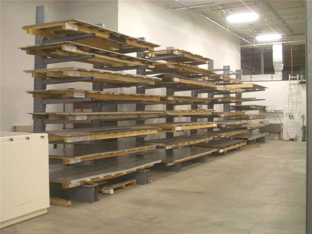
Steel Sheet Metal Flat Stock Sheets Denver Colorado H H Metals

Home Made Sheet Metal Brake Pirate4x4 Com 4x4 And Off Road Forum Sheet Metal Brake Sheet Metal Bender Metal Bending Tools

Miller Welding Projects Idea Gallery Tubing Bender Welding Projects Metal Working Projects Metal Working

Homemade Bending Tool Sheet Metal Brake Youtube Sheet Metal Brake Sheet Metal Bender Sheet Metal

Simple Sheet Metal Brake No Welding Sheet Metal Sheet Metal Brake Sheet Metal Bender

Diy Sheet Metal Repair Patching Youtube Welding Projects Welding Welding Jobs

36 In Metal Brake With Stand

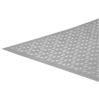
Sheet Metal Hole Punch And Dimple Die Imgur Hole Punch Sheet Metal Metal Shaping

Sheet Metal Notchers For Race Car Fabrication Metal Working Tools Metal Metal Shaping

Crater Maker 3 8 4140 Hardened Dimple Dies Sheet Metal Fabrication Sheet Metal Tools Metal Tools
Https Encrypted Tbn0 Gstatic Com Images Q Tbn 3aand9gcqixqh95xphsspyaxiuwtw11ktvln5thwpqlxg83vqt2ywsiwnz Usqp Cau

Sheet Metal Bender Brake The Make Diy First Use Stainless Steel Bbq Youtube Metal Shop Metal Bender Metal Working Tools
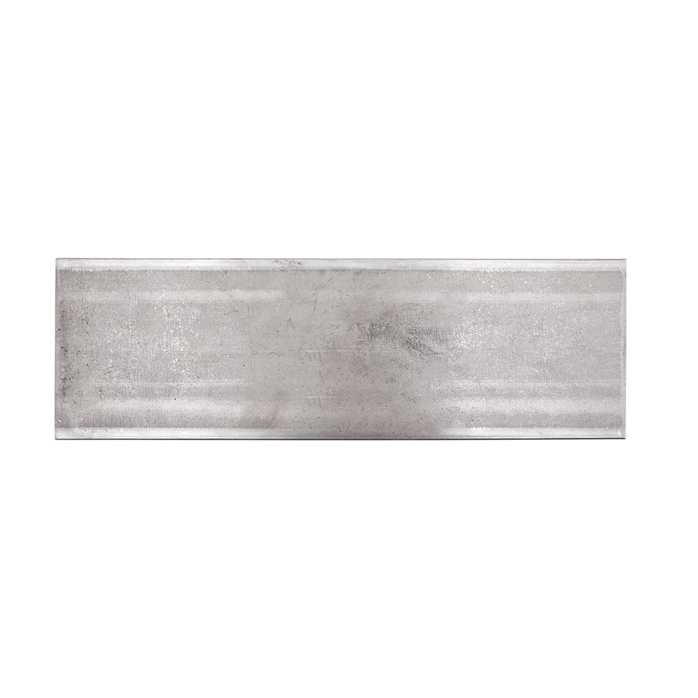
Steel Sheet Metal Metal Stock The Home Depot
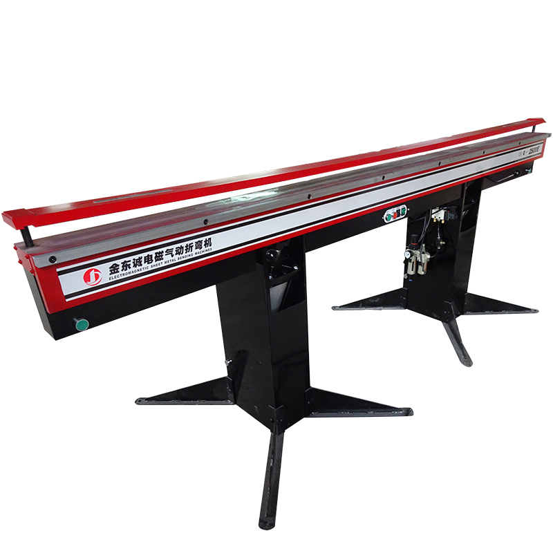
China Cheap Price Sheet Metal Bending Machine 2mm 2500e Powered 2500mm X 1 6mm Electromagnetic Sheet Metal Folding Machine Jindongcheng Manufacturer And Supplier Jindongcheng

Amazon Com Eastwood Sheet Metal Fabrication Bead Roller Kit Forming Mandrels Automotive Sheet Metal Fabrication Metal Bending Tools Metal Working Tools

1969 Camaro Custom Hood Vent Fabrication Custom Metal Fabrication Sheet Metal Fabrication Metal Fabrication

New Sheet Metal Knockout Punches By Bramley Sheet Metal Hand Tools Metal Working Tools Sheet Metal Fabrication

Something Most People Don T Know About Me I Read A Lot I Don T Read Romance Novels Though Seriously I Never Do Metal Shaping Metal Sheet Metal

Dd1005 Jmr 5 Piece Dimple Die Set Metal Fabrication Metal Tools Sheet Metal Work

Pin On Metal Fab Tools

Clean Google Image Result For Http Www Designshare Com Awards Imagefiles 134 Photo1 J Shop Layout Welding And Fabrication Shop Interior Design
Aluminum Sheet Metal At Lowes Com

Close Up Of Hot Rolled Steel Countertop 1 4 Thick Plate Steel Metal Countertops Stainless Steel Countertops Island Countertops

Pin On Sheet Metal Working Roller

Metalace 44f U Weld English Wheel Kit Build Your Own Frame English Wheel Metal Bending Tools Metal Working Tools

Building A Fender Part 1 Youtube

English Wheels Form Eckold Very Sturdy And Rigid English Wheel Sheet Metal Tools Metal Working Tools

Stainless Steel Flexible Hose Assembly With Different Fittings Email Carlsionlu Aliyun Com Www Hydraulichosecn With Images Flexible Metal Hose Metal Hose Flexible Joint

How To Make An Interesting Art Piece Using Tree Branches Ehow Sheet Metal Tools Planishing Hammer Metal Working Tools

Sheet Metal Patches Bodywork Vintage Trailers Restoration Vintage Camper Remodel Vintage Camper

Steelball 2260g 227g 1040g 508g 227g Steel Ball 2260g 20g 82mm Steel Ball 1040g 10g 63mm Steel Ball 508g Glass Ball Safety Glass Laminated Glass

2 Pack Air Filters Spark Plugs Ignition Coils And Carburetors Ignition Coil Go Kart Spark Plug

Pin On Planishing Hammer

Sheet Metal Birdfeeder Metal Working Projects Sheet Metal Metal Projects

