Bend Relief Size For 16 Gauge Sheet Metal
Bend Allowance Sheetmetal Me
K Factor Sheetmetal Me
Sheet Metal Hems Sheetmetal Me

Sheet Metal Understanding K Factor
What Sheet Metal Shops Wish You Knew Reasonable Tolerances Grain Direction And The Base Flange
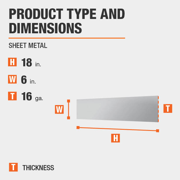
Everbilt 6 In X 18 In 16 Gauge Plain Steel Sheet Metal 801467 The Home Depot

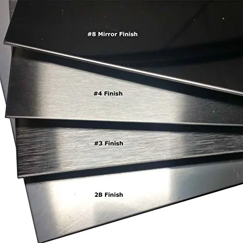
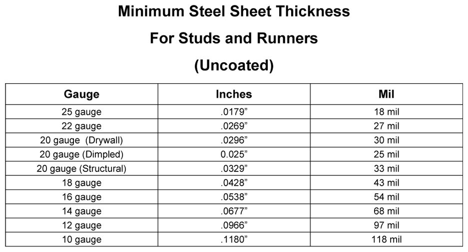
When working with sheet metal it is common for the term gauge to be used someone unfamiliar with the gauge system may not understand what is meant by 18 gauge steel for example.
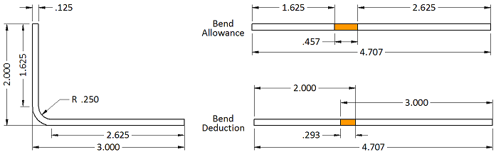
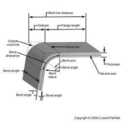
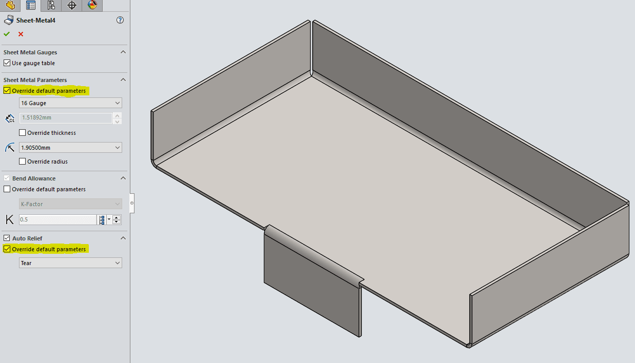
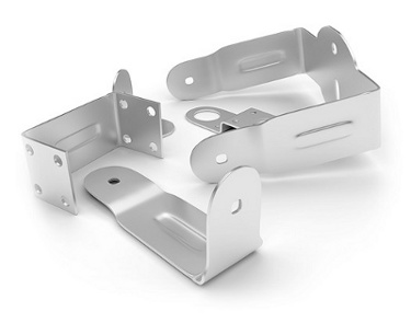
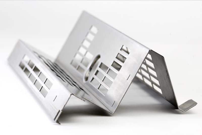
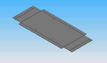
Bend relief size for 16 gauge sheet metal. The bend allowance and bend deduction are two measures that relate the bent length of a piece of sheet metal to the flat length. For example if you make a partial flange as above using all the defaults the software makes relief cuts at the end of the bends as shown to the right. When designing sheet metal parts and enclosures it is helpful to use these values as the basis for your design. Since commercial sheet metal bending can be done with less concern for stresses caused during forming operation the radius can be near zero for thin sheet metal.
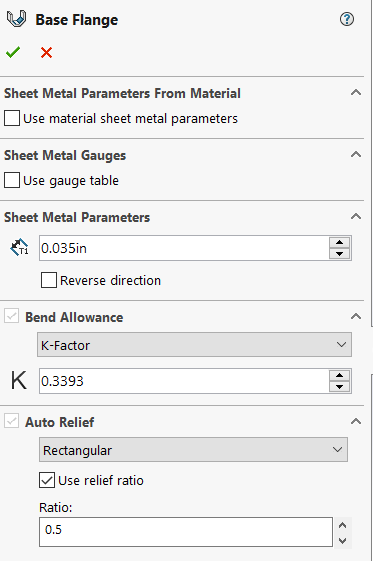
Bend radii minimum bend sizes. Therefore the bend allowance added to the flange lengths is equal to the total flat. You should also incorporate the use of bend relief cuts with a thickness of at least the thickness of the material with strong preference for bend relief cuts of a thickness. First utilize minimal bend radius of internal bend radius equal to material thickness.
As this happens you gain a small amount of total length in your part. Bend radii minimum bend sizes it is most economical to use a single bend radius throughout the design but if necessary you can utilize multiple radii. When the sheet metal is put through the process of bending the metal around the bend is deformed and stretched. One benefit of a bend relief is that it makes the part easier to produce.
Likewise when you are trying to develop a flat pattern you will have to make a deduction from your desired part size to get the correct flat size. Likewise when you are trying to develop a flat pattern you will have to make a deduction from your desired part size to get the correct flat size. The bend allowance describes the length of the neutral axis between the bend lines or in other words the arc length of the bend. When the sheet metal is put through the process of bending the metal around the bend is deformed and stretched.
The minimum bend radius data shown in these charts is measured to the inside of the bend. Use this document to choose values that are both manufacturable and meet your needs. If it is ok for the metal to rip the minimum bend relief is zero. To eliminate this a bend relief is added so the edge of the sheet metal is perpendicular to the bend.
Bend radii and minimum bends are limited to certain values or ranges which are determined by the equipment and tooling combinations available to the manufacturer. To help this blog will explain the gauge system and features a sheet metal gauge chart. There are two things that can be done to reduce the risk of sheet metal tearing. In general a minimum bend relief is equal to the material thickness plus the inside bend radius.

Sheet Metal Gauge To Mm Gauge To Thickness Chart Download Sheet Metal Is Metal Formed By An Industrial Process Into Sheet Metal Gauge Metal Gauge Sheet Metal

Pin On Tables Charts For Conversions Et Cetera
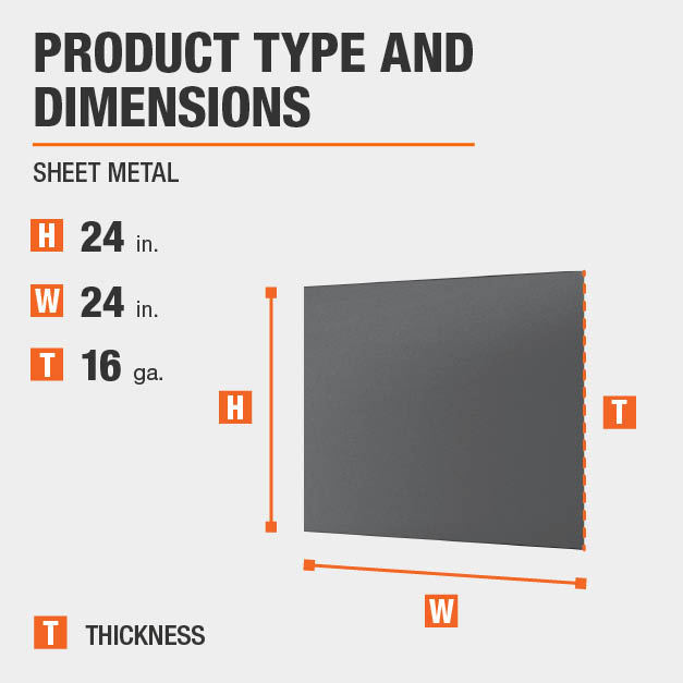
Everbilt 24 In X 24 In 16 Gauge Plain Sheet Metal 800657 The Home Depot

Sheet Metal Gauge Chart Sheet Metal Gauge Metal Gauge Sheet Metal
Bend Allowance Calculator

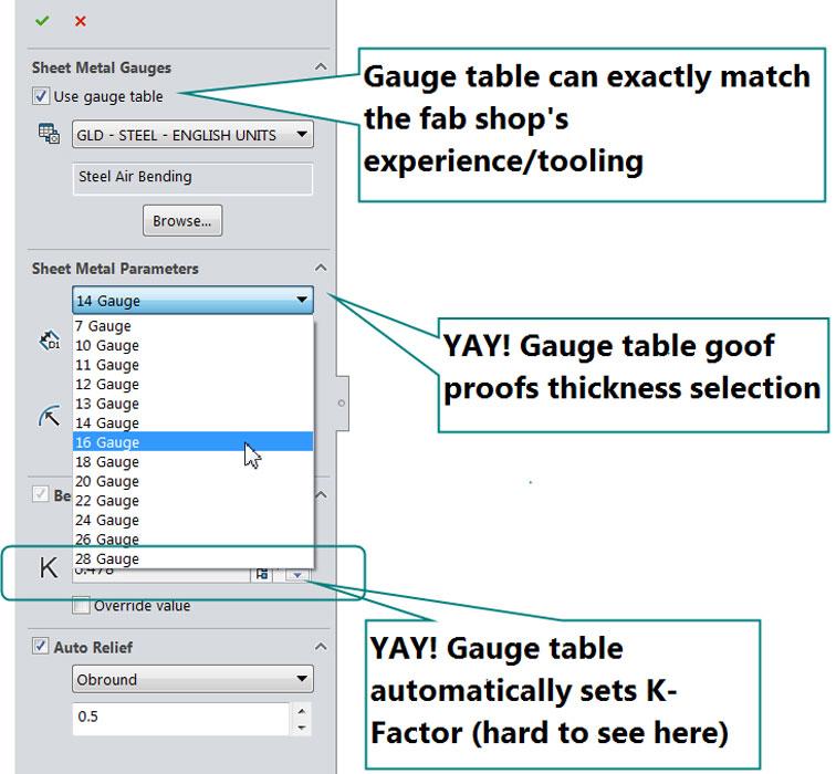
How To Create A Custom Solidworks Sheet Metal Bend Table
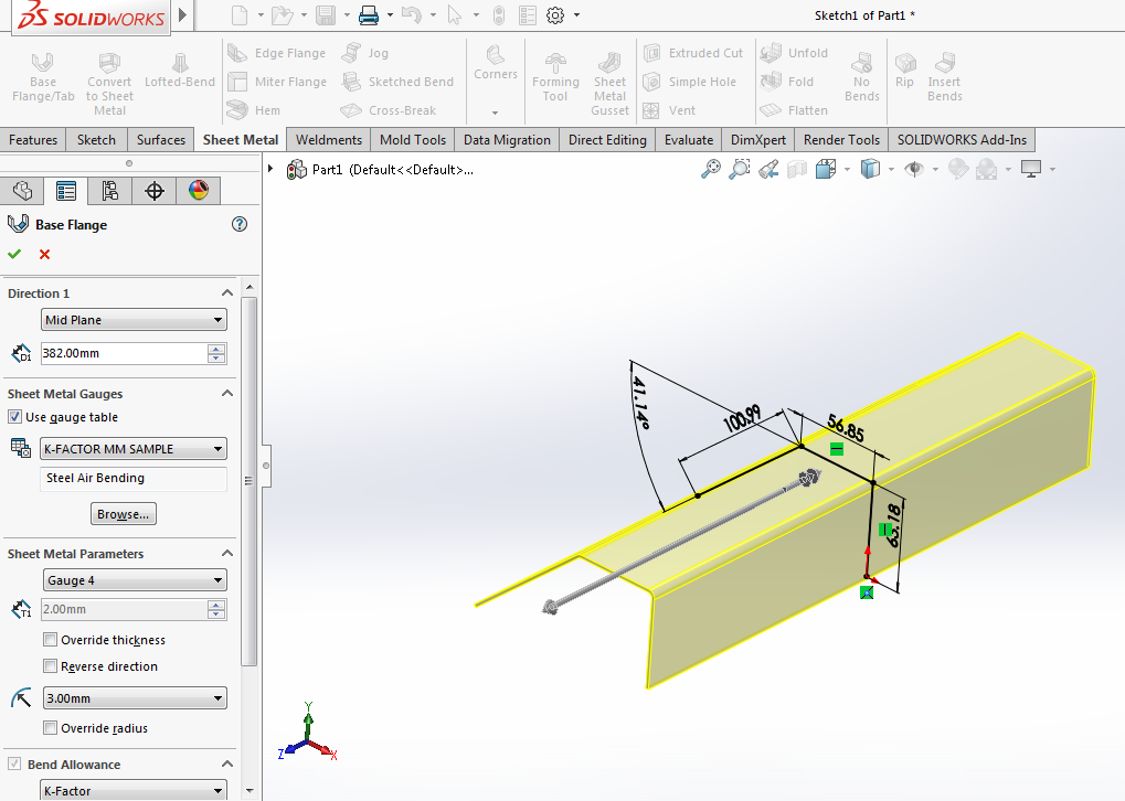
Sheet Metal Success In Solidworks Engineers Rule

Metal Gauge Chart Metal Gauge Steel Sheet Metal Stainless Steel Sheet Metal
16 Gauge Stainless Steel Sheet Metal 1 4306 Stainless Plate Buy 16 Gauge Stainless Steel Sheet Metal 16 Gauge Stainless Steel Sheet Metal Sheet Metal 1 4306 Stainless Plate Product On Alibaba Com
Solidworks 2017 Sheet Metal Options

Designing For Sheet Metal Fabrication White Paper

Solved Problem With Sheet Metal Corners After Adding Corner Seam With Overlap Autodesk Community Inventor
Solidworks Sheet Metal Gauge Tables Perception Engineering

How To Control The Warping Of Parts In Thin Sheet Metal Fabricating And Metalworking

Argentium Silver Sheet Metal Price Per 6 Jewelry Making Cleaning Jewelry Jewelry Making Supplies

B S Gauge To Mm Inches Conversion Contenti Gauges Size Chart Metal Art Jewelry Beads And Wire
Https Docs Plm Automation Siemens Com Data Services Resources Se 109 Se Help En Us Selfpacedext Pdf Mt01419 Pdf

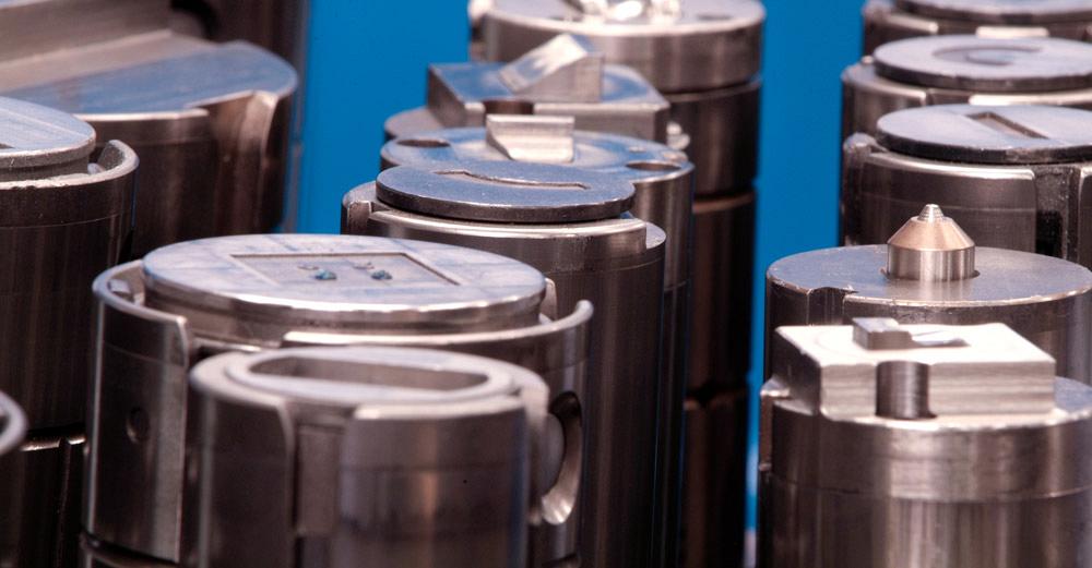
Polyurethane Die Pads For Metal Forming Polyurethane Products
Https Encrypted Tbn0 Gstatic Com Images Q Tbn 3aand9gctf5 Nxksu4pilv5ywyfyl1 Wjg1jit Cavw4ekf14vx5cfm6oo Usqp Cau
Light Gauge Metal Stud Framing Buildipedia

Metal Cone Layout Google Search Geometri Tasarim Konteyner Ev

Box And Pan Sheet Metal Brake Manual Sheet Metal Bender Baileigh Industrial
What To Do When Cutouts And Other Components Need To Be Placed Close To A Bend Protocase Blog

Pin On Tools For Metal Working
Https Oneplm Com Wp Content Uploads 2019 06 Siemens Plm Solid Edge Sheet Metal White Paper Pdf

Sheetmetal Workbench Freecad Documentation
Designfax Technology For Oem Design Engineers

Hydraulic System Diagram Hydraulic Systems Log Splitter Hydraulic Winch
Https Www Buildsite Com Pdf Atas Mca Metal Roof Installation Manual 1280250 Pdf

Everbilt 12 In X 24 In 26 Gauge Zinc Plated Sheet Metal 801537 Steel Sheet Metal Steel Sheet Zinc Plating

Sheet Metal Roller Plans Thorough Professional Sheet Metal Roller Sheet Metal Fabrication Sheet Metal
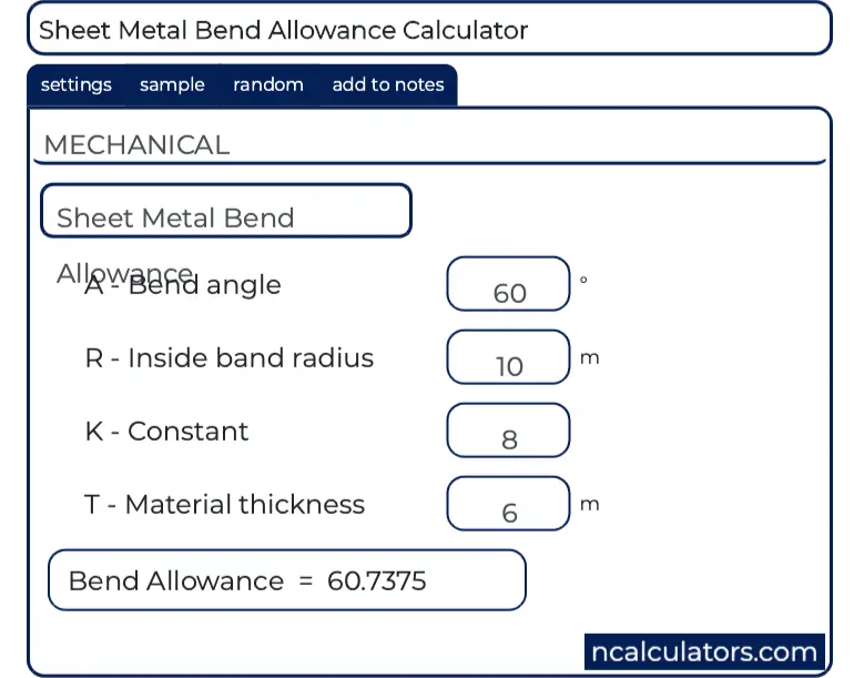
Sheet Metal Bend Allowance Calculator
Sheet Metal Fabrication Basics 7 Strategies For Punching Success
Tips For Bending Sheet Metal Make It From Metal
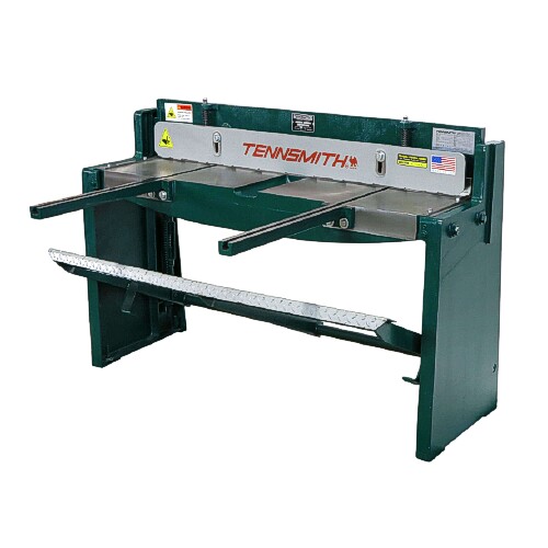
Kick Shear Foot Shear By Tennsmith 52 Inch 16 Gauge Sheet Metal
Sheet Metal Forming
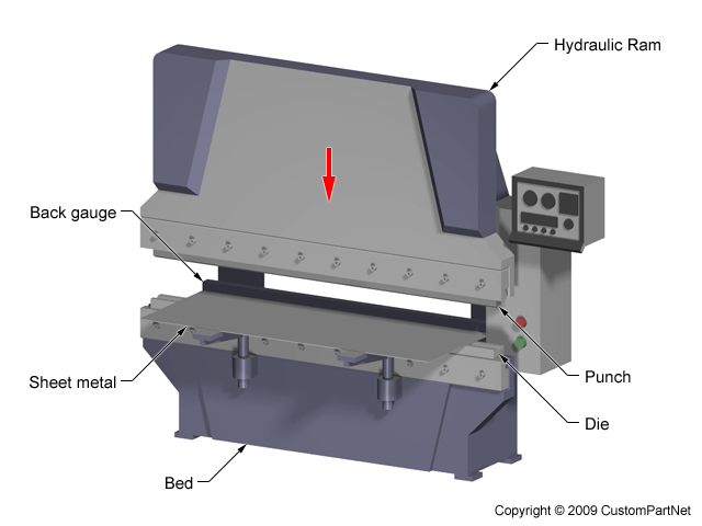
Press Brake The Ultimate Guide 2020 Updated Machinemfg

Sheet Metal Gauged Earrings 9 Steps With Pictures Instructables

12 X 10 Gauge Sheet Metal Roller Slip Roll Rolling Metalworking Brass Steel Metal Bending Tools Sheet Metal Roller Sheet Metal Fabrication

Pin On Process
Weld Sequencing Keep Your Projects From Warping Youtube

Design For Sheet Metalworking Ppt Download
